Read the drawing
Extract candidate casing sections, depths, and other well details from the supplied schematic.

ILLUSTRATIVE CASE STUDY
From a well schematic to a digital wellbore.
An illustrative workflow for turning engineering drawings into structured well data.
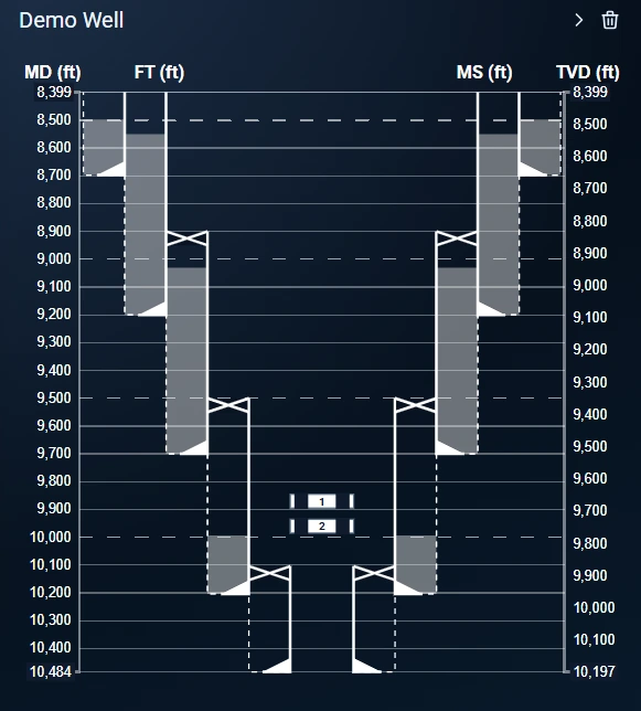
A well engineer receives a schematic as a PDF. Casing sections, depth references, and formation information need to become structured data that another engineering tool can use.
Extract candidate casing sections, depths, and other well details from the supplied schematic.
Apply engineering checks and identify missing values, conflicting labels, or ambiguous sections.
Let an engineer inspect the digital wellbore alongside the drawing and resolve flagged items.
The example ends with a reviewable digital wellbore rather than a fresh manual transcription. The source drawing and unresolved questions stay available to the engineer.
Tell us what your team needs to review, calculate, or extract.